Wheel dimensions and sizing methods can seem a bit complicated at first glance and are best explained using a series of diagrams. Most of the information supplied on this page Triumph specific, but will apply in principle to all car wheels. If you find incorrect info here, or feel something MUST be added, please use the contact link.
Measuring Bolt Pattern:
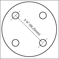
 The adjacent diagram shows a hub with a 4-bolt pattern, which is what you’ll find on the majority of Triumph models. Bolt Pattern is also referred to as ‘Stud Pattern’, PCD (Pitch Circle Diameter), BCD (Bolt Circle Diameter) and ‘Lug Pattern’.
As is shown by the dotted line in the diagram on the left, the measurement should be taken between the centres of two opposing studs.
Small-chassis Triumphs (GT6, Spitfire, Herald, Vitesse)
A 4-bolt pattern.
3 ¾” (95.25mm) between centres [as shown in diagram].
Large-chassis (Stag, TR, 2000)
A 4-bolt pattern.
4 ½” (114.3mm) between centres.
Rim Sizing:
 The dimensions below will greatly influence where a wheel sits in relation to the car body, including how much it protrudes – and whether the tyres will rub on panels, chassis or suspension structure.
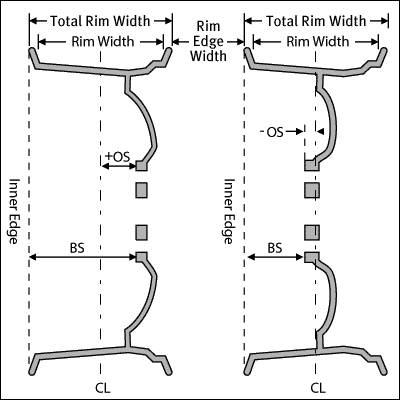
Below is an explanation of each element appearing in the adjacent rim cross-sections.
Rim Width:
This is the measurement between the inside surfaces of the inboard and outboard flanges. It can also be described as the distance between the inside edges of the inner and outer bead seats and is generally supplied to help with rim-to-tire matching. If a rim width measurement is sought to accurately work out ‘Offset’ or ‘Backspace’, then ‘Total Rim Width’ is needed (see below).
Total Rim Width:
This measurement is REAL width of the rim. It is measured from the outside edge to the inside edge of the rim. It will always be wider than the published common widths. For example, a Weller Steel listed at 5.5J has a Total Width of 156.5mm. This is because we have to take ‘Rim Edge Width’ into consideration (see below).
Rim Edge Width:
This is the measurement of the material thickness of the edge flanges, or walls as some call them. If this is added to the ‘Rim Width’ twice, it should equal the ‘Total Rim Width’. So for the example wheel above, the ‘Rim Edge Width’ is 8.4mm. Thus we can see that 5.5″(139.7mm) + 2 times 8.4mm = 156.5mm as stated.
Centerline (CL):
This measurement is the ‘Total Rim Width’ divided by 2. It is important when calculating ‘Offset’.
Backspace (BS):
This distance is measured from the wheel mounting surface, to the ‘Inner Edge’. This is also sometimes called the ‘Backside’ or ‘Rear Spacing’.
Offset (OS):
Offset is the distance between the ‘Centreline’ and the wheel mounting surface (also sometimes called the mounting pad). When stamped or engraved into wheels this measurement is often accompanied by the letters “ET” which is short for “Einpress Tieffe”, German for offset.
Hubcentric and Lugcentric Rims:
The rims used on the TR7 and TR8 are ‘Hubcentric’, and differ from those used on other Triumphs which are ‘Lugcentric’. The difference is to do with the way the rim is located on the hub; its fairly fundamental and should be understood if you intend to use TR7 or TR8 wheels on a previous model.
Hubcentric (TR7 & TR8):
 With this method, the central hole in the rim sits directly on a machined tapered (usually) surface which is part of the hub itself and protrudes through the hole. The load-bearing surfaces are the inner edge of the rim centre cut-out and the hub taper (indicated in RED). When using a hubcentric setup, the only function of the lug-nut is to press the rim against the face of the hub, and not to centre the stud within its hole. There is usually a gap around the stud and lug hole which reduces the chance of sheared studs.
From a wheel centering point of view, this system is almost perfect. Provided the hub has been turned in one operation, the rolling centre can be presumed to be identical to the hub centre; Therefore provided the outer edge of the rim and centre cut-out are concentric, the wheel will sit properly.
Lugcentric (All other models):
 This means that when the rim is mounted on the hub, it is centered by means of tapers on the lug nuts and lug holes. The load-bearing surfaces are between each lug and its seat on the taper (indicated in BLUE). The centre hole in the rim effectively ‘floats’ around the grease cap without touching it.
This system is often considered the inferior method for 2 reasons. Firstly: studs are usually fairly thin in comparison to the hub centre shaft itself, and are prone to bending, stripping and shearing under stress. Secondly: When hubs and rims are produced, there is a possibility that the lug or stud holes might be drilled slightly off centre, and this means that when bolted on, the rim will likely not be concentric with the hub. Its probably worth saying that even if the studs, holes and tapers are perfectly positioned, a slightly bent stud will still result in an off-centre wheel.
Did you find this useful? Please let me know with a tap/click:

 - +34 thumb, 40 overall.
very interesting. I have tr7 wheels on my 1500 spitfire… oops… And wondering what easy fix you can advise to modify hub to be hubcentric? Will tr7 hub fit on spitfire? Or have hub centric ring mschined to fit spitfire hub. ?
Syeve
Hi, long time since I’ve thought about any of this, and you’ll want to double-check this, but:
Does the hole in the centre of the wheel already clear the hub ok? If so I think your simplest solution (if these are Steel TR7 wheels) is to countersink the lug-holes to accept tapered lug nuts – likely the ones you already have. Others have done this with success.
Another consideration is the lug size/strength. The stock 3/8” studs are weedy. Some have fitted much beefier Landrover Freelander studs which fit into the hub bodies ok, but is a much thicker M12 thread. Just found a link: http://auskellian.com/paul/links_files/upgrade_spitfire_wheel_studs.html
(I note that site has ‘borrowed’ the info from this page, images and all, elsewhere. Oh well)